
Your 3d Upgrade may have shipped with firmware that is slightly out of date. The firmware included in this package is v.6.0.89. The firmware that was preloaded on your board is compatible with the current software, but v.6.0.89 provides features required for the full functionality of this version of MIOConsole3d.
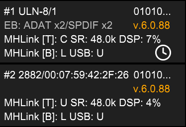
If your board has older firmware, MIOConsole3d will indicate that the firmware is out of date by drawing the firmware version listed in the box status pane in an amber/orange color. If this is the case you should update the firmware using MIOConsole3d at your leisure after you get your system set up.
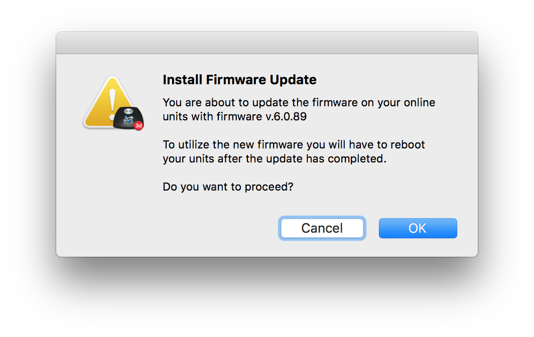
To update the firmware, simply click on the orange firmware version readout, or select the Utilities > Install Current Firmware… menu command. You will see a confirmation alert and if you proceed, the firmware will be updated.
It should not take more than about 30-40 seconds per box to update the firmware.
After the firmware update window disappears, you will need to cycle the power on your boxes for the new firmware to take effect. MIO Console does not reboot the boxes automatically.
The 3d Upgrade provides two different ways for you to connect the hardware to the computer.
With the current software, USB is only appropriate for connecting one box to the computer. USB utilizes the UAC2 class driver integrated in macOS. It supports 12 channels of I/O (12 in and 12 out) at all sample rates. With MIO Console you can adjust the number of I/O channels that are available via USB; if you increase the number of channels, you will limit the maximum sample rate supported over USB. While additional boxes connected to the USB connected box via MHLink may show up in the Console, the firmware does not yet provide a communication path between the Console and boxes chained via MHLink. If you will be using more than one box, you must use the MHLink driver and connection. MIOConsole3d has a preference that allows you to limit the MIOConsole connection to MHLink to allow simultaneous connection of both MHLink and USB in advanced applications.
Note: Support for MHLink aggregation over USB will be provided in a future release.
USB does support connection to other platforms (Win10, iOS, Linux); the device will show up as a class device and will have direct routes between USB and Analog I/O. With the new USB SCP functionality you can manually control USB routing via MIOConsole3d. Configurations running on other OSes have been verified to work, but have not received substantial testing at this time.
3d supports direct connection between your computer and MHLink. In order to connect via MHLink you need:
You may connect through a modern Gigabit Ethernet switch if you want to share the Ethernet port with general networking functions. While using the switch is supported, it is possible that a given configuration or network usage pattern may not be 100% reliable. If you find the shared connection to be unreliable, dedicate an Ethernet port to MHLink.
When using MHLink as the connection to the computer, you can chain multiple boxes via the included short Cat 5e patch cables. The system will automatically recognize the chained boxes and aggregate their resources.
The MHLink Audio driver supports up to 128 I/O (128 in and 128 out) at up to 192k. You may need to use large host buffers for 128 channels of I/O especially at higher sample rates. The driver defaults to 32 I/O. MIO Console provides a menu to control the number of channels provided by the driver; currently you must have MIO Console in order for your I/O channel preference to be re-asserted if you disconnect and reconnect your hardware.
In order to connect to your boxes over MHLink, you must install the MHLinkDriver.
In pb7, the driver installer is integrated in MIOConsole3d.
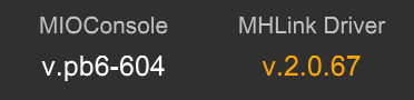
If the driver is not yet installed, or MIOConsole3d includes a new version of the driver than the one that is installed, the MHLink Driver version indicator in MIOConsole3d will be drawn in amber/orange.
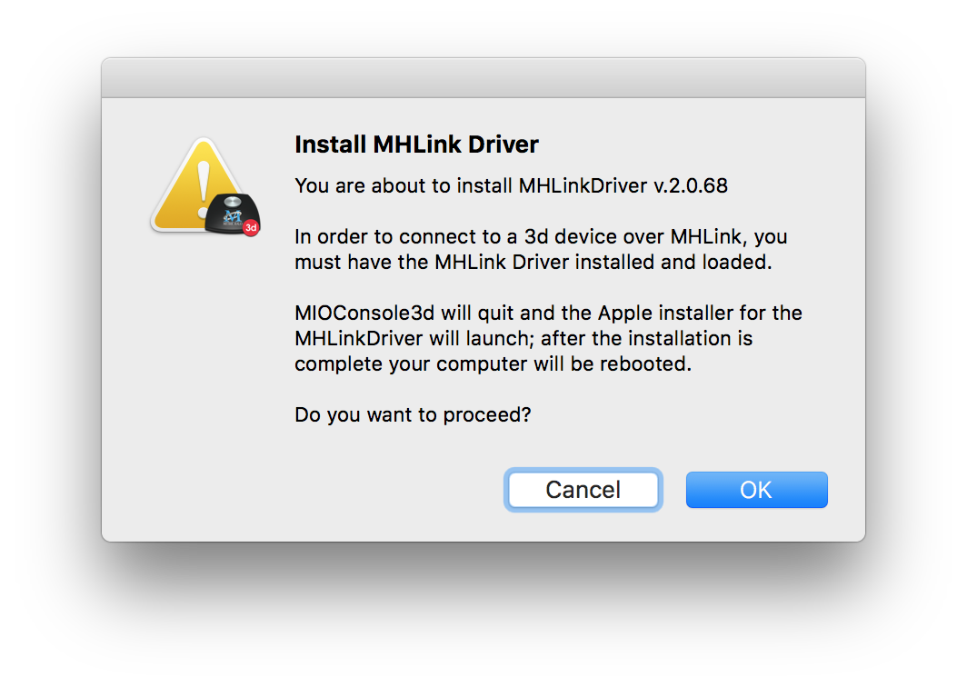
You can initiate the installation of the driver by clicking on the version number or by selecting the Utilities > Install Current MHLink Driver… menu command.
You will see the driver installation confirmation alert which will tell you what to expect from the driver installation process; the actual installation will be done by Apple's installer program.
If you are running on 10.13 or newer, you will need to authorize the driver to load after the first installation of the driver. Please see our Driver Installation FAQ for more details.
The MHLink driver provides control of the Monitor Control gain of the directly-connected ULN-8/LIO-8 box via CoreAudio properties. This allows you to adjust the gain of the MC on the directly connected box via the media keys on the computer keyboard (even if MIO Console is not running).
Note: Steinberg products have a setting that causes them to reset the gain control to 0 dB on launch. This may cause your monitor gain to jump. If you do not want this behavior, you need to disable this preference in Cubase/Nuendo. The setting is “Set Device Attenuation to 0 dB” inside the “Control Panel” of the audio device. This needs to be off.
The Driver will discover devices connected to the computer over Ethernet. Currently the driver, console and firmware do not provide any support for arbitrating or sharing the hardware between multiple computers. Only run one copy of MIO Console at a time if multiple computers can see the same 3d hardware via the network.
If you connect multiple 3d units to the network, each will appear in its own MHLink clock domain (MHLink cannot heal the clock across a switch). To have an aggregated system, the hardware must be daisy chained via the MHLink ports, with one end of the chain connected to the computer or the network. Do not create Ethernet loops.
The main control software for 3d is MIOConsole3d. With the current firmware, you will need to launch MIOConsole3d to establish the routing within the system. If you will not need to make changes to the routing, you can quit MIOConsole3d after the routing is established. Alternatively, you can close MIOConsole3d’s windows or hide the application; this will reduce the CPU load of MIOConsole3d to almost 0.
MIOConsole3d does not implement ConsoleSync yet, so re-launching MIOConsole3d will cause a short audio dropout as the hardware configuration is re-asserted.
When you launch MIOConsole3d for the first time, it will discover the hardware that is attached.
If you do not have any hardware attached, there will not be much to see. The software does not currently support creating hardware “virtually” so you will need to have hardware attached to work with the software. Once you have attached hardware, MIOConsole3d will save its state to your hard drive, and then you can load and modify saved configurations without any hardware attached.
MIOConsole3d and MHLink organizes your hardware into “MHLink Domains”.
An MHLink Domain is a set of boxes that is connected together via an MHLink daisy chain. The MHLink daisy chain provides a clock and routing backbone that is managed by MIOConsole3d.
If you have more than one domain (either connected or via saved states), they are managed as separate domains in MIOConsole3d; the UI for MIOConsole3d allows you to control one domain at a time; the currently active domain is selected from the System Status panel in the Mixer window.
Each MHLink Domain has a Root box. This is the box that has the direct connection with the computer running the MIOConsole3d. If you reconnect the boxes in a different order, and the directly connected box changes, it will be recognized as a different domain. So, be consistent; choose the box that you will use as the root box of the system and stick with it.
MIOConsole3d will re-route automatically if you change the order of the boxes that follow the Root box.
Note: MIOConsole3d does not currently support mapping the configuration between different boxes or different domains. We will be providing a complete remapping solution in a future release.
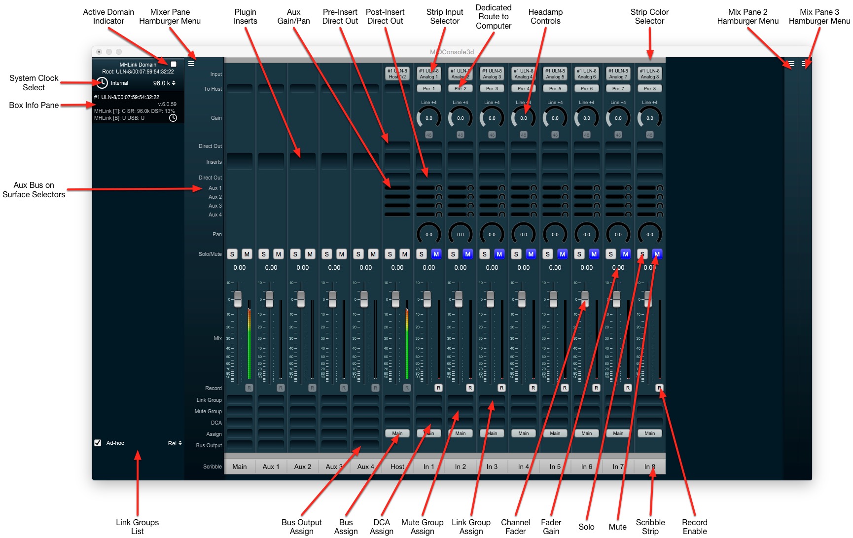
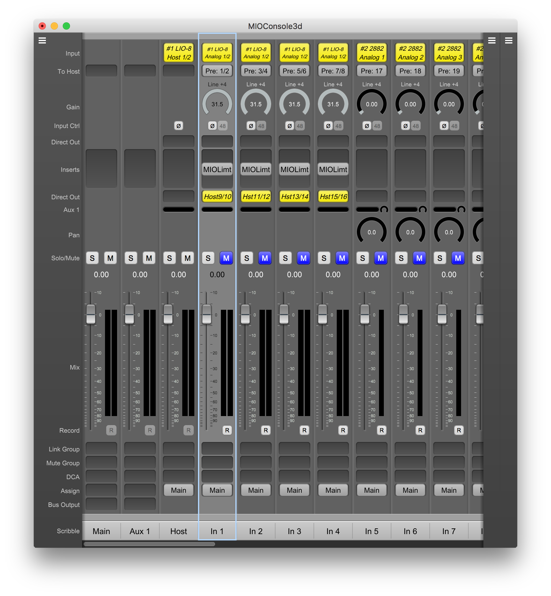
The Main Console window has two primary areas; the System Status pane on the left and the Mixer pane on the right. You can hide the System Status pane if you like.
The System Status pane is further divided into the Domains pane (top) and the Link Group pane (bottom).
The Domains pane lists the MHLink domains known to MIOConsole3d (either due to a current connection or from being restored from a file). Each domain has a domain header which indicates the domain root box, the domain clock source and sample rate, and if the domain is the currently selected domain. The clocks source, sample rate and selection indicator are also controls; you can change those parameters by clicking on the controls.
Below the domain header are listed each of the units in the domain, and the unit configuration and status is include in each unit pane. The units are listed in daisy chain order.
The Link Group pane lists all the link groups in your mixer; you can enable or disable them, rename them, or change the link mode from the link group pane.
There are actually 3 Mixer panes in the window; two are collapsed by default. Each Mixer pane can provide an independent view of the mixer. You can choose the types of strips and strip elements that are shown in each pane independently. If you choose to show no strips in the pane it will collapse.
By default the leftmost mixer pane is configured to show all strip types, and all strip elements. The master strips for the busses are created first and will be displayed leftmost in the pane. You can click and drag the strips to reorder them. The strip order set in the mixer pane will also be used for the control surface if you use one.
The hamburger menu for each pane allows you to control the configuration of the pane.
Most of the elements of the mixer are self evident, but there are a couple of items that are worth pointing out:
The Mixer Menu provides global commands for the mixer; in particular, there is the "Configure Mixer" command which is a bit different than what was in 2d. This command allows you to set the Main bus width, enable or disable Hard Mutes, control the number and configuration of the Auxes, Groups, DCA's and Mute Groups.
MIOConsole3d utilizes the abundant routing resources provided by the 3d hardware and MHLink to automatically manage the internal and box-to-box routing for you. Similarly, clocking is also automatically managed via MHLink; all boxes in the domain are automatically synced to each other and the entire domain is synced to the clock source you select for the domain.
Rather than worrying about how audio gets from one box to the other, you just deal with audio ports and busses.
MIOConsole3d automatically configures the mixer and routing when new hardware is discovered using the following rules to make it so that you don't need to configure things for simple use cases.
When a new domain is created:
When additional new hardware is connected to an existing domain:
If you want to add digital inputs you can do that manually. You can also add more inputs from the computer to the mixer (e.g. for using the 3d Mixer to mix the outputs of your DAW) or adjust the routing to the computer from the box.

By default, MIOConsole3d will create a Monitor Controller for your domain. If you don't want to use the monitor controller, you will need to delete the output paths in order to return Analog 1+2 and the headphone outputs to manual control.
MIOConsole3d automatically adds all the busses as sources for the MC. You can also manually add other sources (e.g. from the computer or from physical inputs). You can also add more output paths.
The controls in the MC are relatively self evident; the speaker icons will mute the associated output channel when toggled on. The "Monitor > Speakers Toggle Solo" menu item allows you to switch the speakers to act as solos rather than mutes.
The Monitor Controller in MIOConsole3d also supports attaching a +DSP graph to each output path (use the Monitor > Edit Current Monitor Output Graph menu command to add output processing). This can include EQ, Bass Management, etc.
The Output Cue section provides you with an arbitrary number of output controls.
Each cue can be driven from any of the busses in the system, or it can be set to derive its input from the currently selected source in the Monitor Controller (MC).
Each cue has an independent output path which can be set to any of the MC supported output types. Each cue controller uses the MC engine for its control of routing, gain, delay and output graph processing, so it can do all the things the MC can do.
With the introduction of the Cue section, the default monitor configuration for a newly discovered MHLink Domain has changed (a new domain is discovered when you connect a box to the computer for the first time, or after you trash your preferences and then connect a box).
Rather than assigning the Headphone output for the directly connected box to a MC output path, it is assigned to a Cue controller. When it was assigned to an output path, you had to choose between Monitors and Headphones. As a Cue, the headphones are automatically multed from the Monitors and have their own independent gain control.
The Cue Controls are in their own window which is resizable.
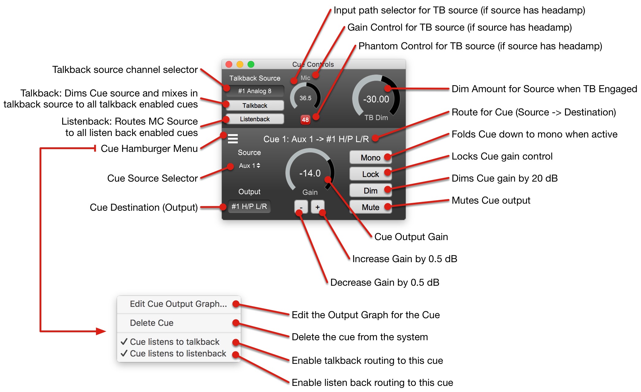
There is a menu item in the Monitor Menu to add a new Cue “ Monitor > Add Cue Controller”. By default, Cue Controllers are setup with the following parameters:
To configure a new Cue (or an existing one) click the "Output" Path selector control in the bottom left of the Cue; you can configure the Cue Output just like you would configure a MC Destination. The Name of the Cue Output is used as the name of the Cue.
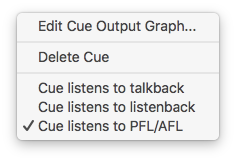
Each Cue has a Hamburger Menu; you can use the Hamburger Menu to control the following items:
Please note that Cues are not Mixes. Cues are output points with gain and routing controls that can be fed by specific mixes, the current monitor controller source, or a mix of a source and the talkback signal. They serve as named output mults with direct access to associated output gain controls.
Cues form the basis of the routing points for Talkback and Listenback.
There is a menu command in the “Monitor” menu (along with an associated key command) to add a new Cue controller
There are two new key commands for triggering talkback and listen back:
By default, newly created Cues are not slaved to either talkback or listen back (currently you need to enable either or both of these per cue).
Talkback provides the ability to route a specific input to any sub-set of the cues in the system; it also allows you to control the amount that the Cue source signal is dimmed when talkback is active (from -6 dB down to -60 dB [which is effectively mute]). The Talkback signal is mixed with the selected source.
When talkback is enabled, the following happens:
When talkback is disabled, the following happens:
Listenback provides the ability to route the source that the engineer is currently monitoring through the MC to any sub-set of the cues in the system. This allows playing back a mix of the take to any or all of the monitoring cues in the system without having to re-patch.
When listenback is enabled, the following happens:
When listenback is disabled, the following happens:
This build also adds PFL/AFL support for non-destructive soloing. If PFL/AFL functionality is not something you need, you don’t need to change anything, and it will all keep working as it always has with solo-in-place mode.
Let’s start by describing what the different modes are, and why you might want to use each one:
SIP - Solo-in-place is the solo that everyone is used to in DAWs. It is “destructive” in the sense that the solo is done on the bus itself, and the active mix is replaced with the submix of the currently soloed channels.
It is simple to describe and understand. It is completely appropriate for normal studio mix/production work where the current mix is only being used for monitoring and making mixing decisions.
In the context of MIO Console, solo-in-place mode is applied per-bus, so, for example, you can solo channels in your main mix without having any effect on your aux busses (so monitor mixes will continue to run untouched).
Again, this is the default, and if you are happy with it you don’t need to change anything.
The other two modes (PFL & AFL) utilize a dedicated bus for soloing, and leave all the other busses in the system untouched when channels are soloed.
These are a bit more complex because they involve routing as well as soloing. So why would you want to use either of these modes?
Well, these solo modes are appropriate for operations where you need your mix to be unaffected by any soloing you need to do for your own transient monitoring needs.
For example, if you are mixing a live show, your main mix is sent to the PA. If you want to solo a specific channel to be able to make, say, an EQ decision, you certainly don’t want the main mix (which is going to the PA) to only have the soloed channel; rather you would want it to go to a dedicated monitoring system that you are using for your solo’ed channels (whether a set of headphones or the studio monitors or something else), while the primary mix is undisturbed.
Even if you are doing live recording that doesn’t involve sound reinforcement, you may be sending a two-bus mix to a backup recorder or have a rough mix being recorded on the computer along with the individual channels of the multitrack (e.g. a production mix). In this case, you still would want to be able solo channels without affecting your production mix.
For these sorts of scenarios, we have PFL and AFL.
When one or more channel is soloed when either PFL or AFL mode is selected, the solo’ed channels are routed to a dedicated solo bus. The solo bus is routed as the source to any of the Monitor or Cue controllers that have been set to listen to PFL/AFL; that source routing overrides the selected source for the relevant controller while the solo is active. When there are no solos active, then the controller switches back to getting its source from the source that is selected in the controller.
The solo bus input routing is as follows, depending on the solo mode:
Choose the solo mode that works best for you in the Mixer Config dialog. You choose between SIP, PFL or AFL (using the popup menu). This is currently stored as part of the .cnsl3d file, per domain.
The Solo Bus gets a master strip in the mixer. You can use this for a number of different functions:
Now, the flexibility of this system is based upon your ability to determine what signals will source your MC and Cues, and whether or not the MC and/or Cues slave to the solo bus when PFL/AFL is active.
If the MC/Cue is set to Listen to PFL/AFL, then soloing will override its source signal, and source it from the solo bus. This allows you to choose which output get the solo signal, and which ones don’t get overridden.
For example, you might want your Control Room monitors to NOT get the solo signal, so that anyone sitting in your control room continues to hear the complete mix, even when you are soloing onto your headphones. Alternatively, (and this is the default), the solo is reflected on your control room monitors as that’s the primary monitoring setup for your mixing work.
Now, your MC and Cues also have support for source selection, and one of the sources is the solo bus. So you could, for example, have your headphones sourced by the Solo bus; if that’s the case, the cue would be muted until you enable a solo; this would allow you to have HP set up specifically for soloing that did not make any sound until you hit the solo.
For recording, you would probably have your HP getting your production mix, and listen to PFL/AFL so that if you hit solo, you get the solo in your cans, and when you release the solo, you go back to the production mix.
If you solo a master strip, that will cue the master through the solo bus. Note that PFL and AFL are the same in this case; the bus outputs are routed post fader in all cases.
Note that by default, solo is latching and cumulative (so clicking additional channel solos adds them to the solo set). If you hold the command key when clicking a solo button it functions as exclusive solo — it will clear the solo on all other channels.
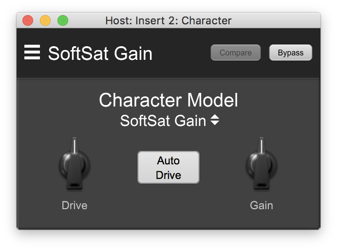
There are two flavors of Character that have been added:
Character is very similar to the Character that was in 2d. It does, however add the following:
These additional features were inspired by the Production Bundle version of Character.
MHCharacter has the the same internal processing, but it wraps the processing in an oversampling block, which can make a difference for heavier distortion (especially with higher drive). MHCharacter does use more DSP power than Character (2x to 3x).
You can access the Digital Port Status and Control UI from the system status pane. Each box has a "Digital Port Status and Control UI" button (which looks like "01010..." in the upper right corner of the pane, circled in red below) in its status pane:
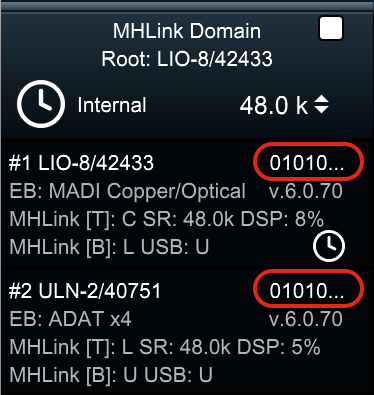
Click the "01010..." to pop up the Digital Port Status and Control UI for that box:
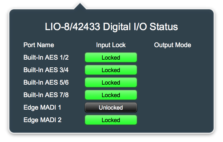
The UI has 3 columns:
The UI will list all the installed ports for the device (so it will also show any digital ports that are installed via EdgeCard).
For most digital port types (AES/SPDIF/MADI) the input can either be locked or not, and there is no configurable mode for the output.
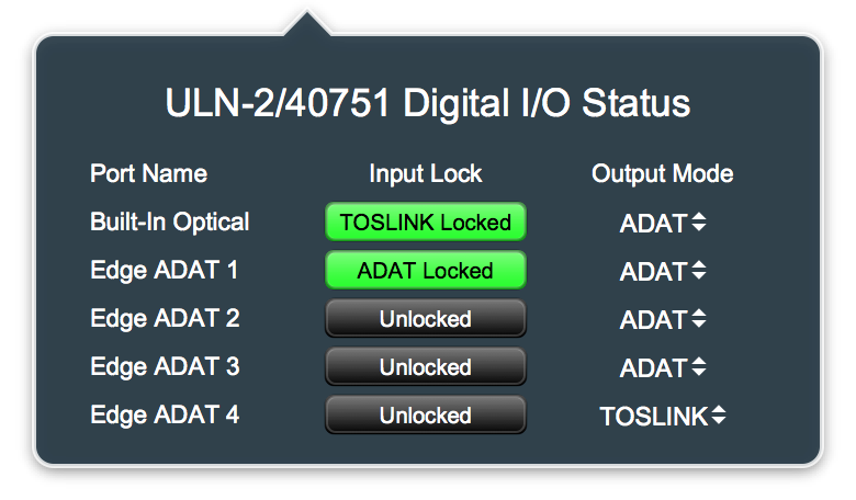
For the ADAT Optical ports each input port can be locked to either ADAT or TOSLINK (Optical SPDIF) or unlocked (if there is no valid input signal of either type on the port). The output ports can either send ADAT (8 channels) or TOSLINK (e.g. Optical SPDIF - 2 Channels). You can select what signal type you want to send on a per port basis with the associated popup menu.
The 3d Card has a SPDIF transmitter and an ADAT transmitter for each Optical Output Port. When you select between the output port mode, you are selecting which transmitter is physically connected to the port. Each transmitter has its own output routing in the system. As a result, when an output port is set to TOSLINK mode, you must route to the associated TOSLINK channels in order to get output. When it is set to ADAT mode, you must route to the associated ADAT channels to get output.
When an input port is receiving TOSLINK the hardware automatically determines the incoming format. The first two channels of each receiver block will carry either the first two ADAT inputs for the port or the SPDIF inputs for the port, depending on the received signal. So you can route from the TOSLINK input channels or from the first two channels of the associated ADAT block. When it is receiving ADAT, you should use the associated ADAT inputs to have access to all of the ADAT channels.
When you use multiple boxes and systems it is possible to get an offline Unit or Domain in your console setup that is now redundant and unneeded. pb5 provides support to allow you to remove these offline items from your setup.
To remove an offline Unit from your setup:
To remove an offline Domain from your setup:
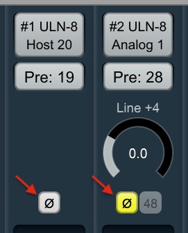
This version of the software and firmware provides support for hardware Polarity Invert for all input strips. This applies to all inputs (Analog, Digital, Host, Bus). Since this is done in hardware, the firmware must be updated for it to function, and it does not consume any additional DSP.
The UI control for this appears in the headamp section of the input strip.
When Polarity Invert is enabled, the input signal to the strip will have its polarity flipped at the router; as a result the polarity flip will be applied to all destinations of the signal including any pre-insert To Host or pre-insert direct out routings.
The Polarity Invert is per-strip; as a result, you can have two different strips with the same input source with independent Polarity Invert settings.
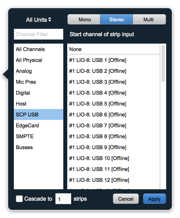
MIOConsole3d now supports setting input strips to Multichannel mode in addition to mono (pan-able) and stereo modes.
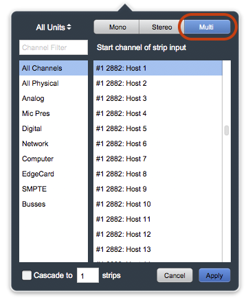
To make a strip multichannel, just select the "Multi" setting in the source selector when choosing the source for the strip; this will automatically make the source match the width of the first bus that the strip is assigned to. As with stereo strips, multichannel strips are direct-routed to the bus(es) they are assigned to.
A number of the plugins included with 3d have internal support for routing an external side chain source to their internal detectors (MIOComp, MIOLimit, MIOStrip). This release of MIOConsole3d exposes the UI required to allow you to choose an external source and route it to the sidechain inputs of these plugins.
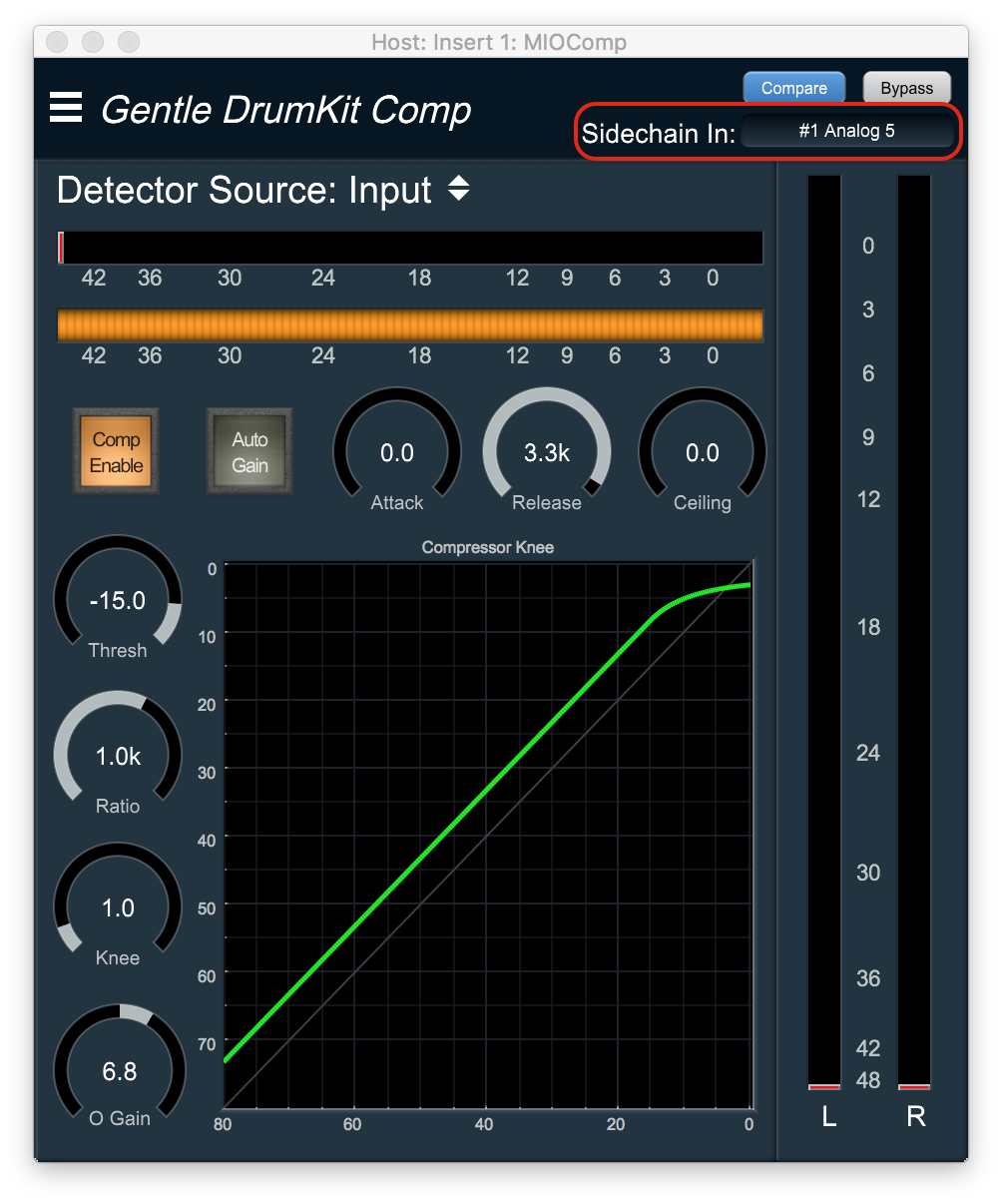
When you display the UI of a plugin that has support for an external sidechain input, the header bar in the plugin window will change to provide a routing control to allow you to select an input or bus as the source for the sidechain input. The sidechain inputs for MIO Plugins are mono, so if you select a bus as the source, the first channel of the bus (generally L) will be routed to the sidechain input, and the remaining channels in the bus will not have any affect on the signal.
The header bar Sidechain In control only selects and routes the source for the sidechain input; this does not automatically select the sidechain input as the signal source for the detector in the processor. Each plugin has controls within the plugin UI to allow you to choose between the sidechain input and the primary signal input as the source to the detector.
In MIOComp and MIOLimit the detector source selector control is in the same place, at the top of the UI labelled "Detector Source".
For MIOStrip, each of the integrated dynamics processors (the Gate and the Compressor) have their own independent detector source selector controls labelled "Src:" and positioned above their integrated pre-detector EQ block controls.
The previous release of MIOConsole3d (pb5) added support for PFL and AFL. Due to an oversight, PFL and AFL always sent mono source signals to the Solo bus as panned center. While this was not original designed behavior, it is a useful mode in some circumstances. This release of MIOConsole3d causes PFL and AFL to send mono source signals to the solo bus with same panning as set for mixing on the strip. It also adds two new modes as options for the solo logic "PFL (mono)" and "AFL (mono)". If either of these modes are selected, soloing will PFL or AFL with mono sources *and* multichannel sources folded down to mono on the solo bus.
The previous release of MIOConsole3d (pb5) had one control over the entire scale of the mixer UI - Strip Width. This control set the width of all the strips, and also adjusted the scale of all the controls within the strips to fit.
This release of MIOConsole3d decouples these controls; it adds a new "Set Mixer UI Scale" command to the Mixer menu, which globally sets the vertical scale of most of the controls in the mixer strip; this makes the inserts, buttons and readouts smaller, and reduces the size of the font used in the strips; it does not have any effect on the width of the strips or the scaling of the fader or meters.
The "Set Mixer Strips Width" command now sets the width of the strips on a per-strip basis; it is applied to the currently selected strips in the mixer UI. The Fader control width and scale is unaffected by the width of the strip. The meters will be automatically scaled to fit in the available space remaining in the strip (which is determined by the width of the strip and the number of meters in the strip).
The default width of each meter in the strip is larger than before, and when the width of the strip is reduced enough, the space between the meters will be removed to preserve the display of the active elements and to ensure that all of the channels are visible on the strip regardless of the width and channel count (e.g. all 8 meters of a 7.1 strip are visible at the narrowest strip setting).
The meters now have the same calibration as the channel faders and the layout has been adjusted so that the dB calibration is shared between the meters and the fader. The visible clip indicator has been enlarged to make it easy to see at all vertical strip scales.
The Monitor Controller now has support for Atmos 5.1.4 and 7.1.4 channel layouts for I/O, including speaker solo/mute support for the overhead channels. There is no special processing implemented to support this and the mixer does not provide support for these bus widths.
These new I/O paths add support for designated overhead speakers and the MC UI has support for Solo/Mute control for the 4 overhead speakers. As with all output paths in the MC you can configure the output graph. The output graph for these new configurations has all the input and output channels, including the overhead channels, available.
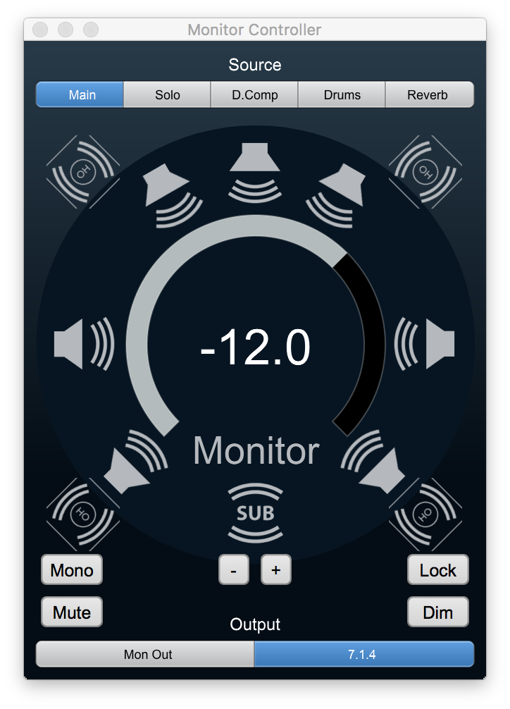
These output paths (Atmos 5.1.4 and 7.1.4) have more than 8 channels in them (10 and 12 channels respectively); you can route the outputs to multiple boxes in your MHLink'ed system, and the monitor controller will automatically handle the system routing and gain control to use multiple boxes as a consolidated monitor controller.
If you have need for additional large channel count output configurations, please get in touch with us to let us know what your needs are, and we will work to add these configurations to the system.
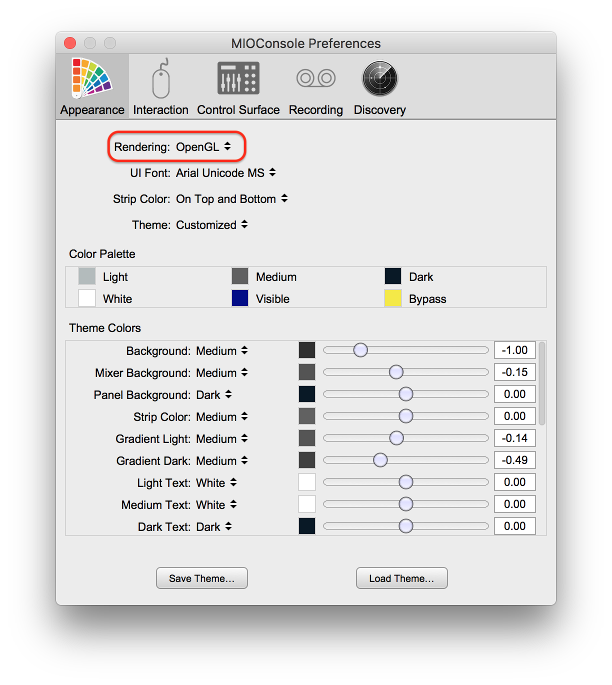
MIOConsole3d allows you to choose what rendering engine is used when drawing the UI. Up until now, MIOConsole3d always used OpenGL. While the default remains OpenGL, with this release you have three options you can choose from:
Use the MIOConsole3d > Preferences > Appearance > Rendering control to choose the rendering engine you would like to use. You will have to quit and relaunch MIOConsole3d for the change to take effect fully.
The Native rendering engine may use a bit more CPU than OpenGL depending on your OS and machine. It does provide better text rendering than the OpenGL engine; text is heavier and antialiased better with the native engine. It may also provide more compatibility with a wider variety of video cards than the OpenGL engine.
The OpenGL rendering engine is the engine that has been shipping with MIOConsole from the start; it offloads more of the task of drawing the UI to the GPU and offers the lowest CPU load.
The Native with OpenGL Record Panel option provides a hybrid; Native is used for all of the windows except for the Record Panel, which uses OpenGL. Scrolling the waveforms in the Record Panel is the drawing operation that uses the most CPU during drawing and benefits the most from being OpenGL accelerated. This may be the best choice for a wide variety of users.
MIOConsole3d now supports explicit routing to and from the USB connector on any unit in the MHLink chain. When used in this way the USB ports are referred to as Satellite Computer Ports.
This new feature allows you to integrate audio from multiple devices without having to purchase additional interfaces. It automatically keeps your devices synchronized with your system and provides device to device routing as well as integrated mixing and processing.
You can connect a sampler running on a another computer and directly mix its outputs with the rest of your sources. You route directly between computers/devices or mult signals to multiple computers/devices - so you can set up a computer or an iPad as an effects rack or backup recorder.
Since iOS devices provide native support for UAC2 (USB audio), you can integrate the output of multiple iOS instruments into your MHLink Mixer via the direct digital link, and you can record real-time performances by routing them to your main recording computer.
You can use the SCP functionality to integrate multiple computers (or iOS devices) into your MHLink mixing engine. Each USB port is available for connection with a USB audio host. The SCP USB source and destination categories in the routing selector popups allow you to select explicit USB channels to route to and from.
To use a USB port as an SCP port, simply connect the device to one of the USB ports on one of the units in your MHLink chain. Then on the device, select the USB interface of the connected 3d unit as the audio interface for the device, signal processing software or DAW.
NOTE: As with all things MHLink, there can only be one copy of MIOConsole3d running on all the computers connected to the boxes, and if multiple boxes will be in the MHLink chain, the computer running MIOConsole3d must be connected via MHLink in order to control the multi-box chain. See below for new functionality that enables the simultaneous connection of MHLink and USB on one computer.
Earlier versions of the 3d firmware interoperated with most modern MADI implementations, but had limitations when connected with older devices, or devices that were operating in a mode consistent with the original AES-10 specification.
 The version of the firmware included in this release, coupled with the new version of MIOConsole3d fully supports the AES-10 specification and interoperates with all possible configurations of the MADI stream. MIOConsole3d now also allows you to control the configuration of the MADI output streams and also detects the format of the incoming input streams.
There are two different ways that the format can vary, both of which have two valid settings; this means MADI streams can have 4 different valid formats:
When running at higher sample rates (e.g. 2x [88.2/96] or 4x [176.4/192]), the number of channels available on each MADI port is divided by the sample rate multiplier (so for 2x rates, it will be 28/32 channels, and for 4x rates it will be 14/16 channels).
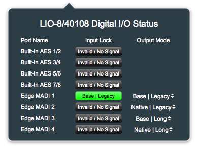
For each output port you can select the output mode from the Digital I/O status for the unit that has the MADI port. You can choose any of the 4 modes listed above.
For each input port, the MADI receiver will automatically detect the format of the incoming stream and decode it. The detected format will be shown in the input lock indicator for the associated port in the Digital I/O status pane.
The previous release of MIOConsole3d only reported if the a given digital input was correctly formated and the decoder for that port was able to recover signal; this was indicated as "Locked" and shown as a green indicator for the Input lock for the port in the Digital I/O status pane.
With this version of the software, we have greatly enhanced the capabilities of the lock detection in the hardware and reporting in MIOConsole3d. Now, the hardware detects the following aspects of the signal on each digital input port:
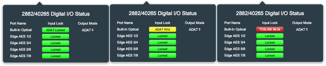
If the signal is either not present or invalid on a given port, the Input Lock indicator will be black, and show the text "Invalid / No Signal". This will be the case if the external device is not connected, turned off, or is sending the wrong type of digital signal to the port.
When the input signal is valid, matches the system sample rate, and is phase-locked to the system clock, the indicator will be green, and show the text "Locked". This will be the case if the external device is locked to the same clock as the 3d system.
When the input signal is valid and matches the system sample rate, but is not phase-locked to the system clock, the indicator will be yellow, and show the text "Wild". This will be the case if the external device is set to the same sample rate as the 3d system, but is not locked to the same clock. In this case the audio may be acceptable, but there will be the periodic sample duplicated or dropped as the relative phase of the two clocks wraps around. This condition is not guaranteed to yield clean audio, and the clocking for the external device should be fixed before using it as a source.
When the input signal is valid and does not match the system sample rate, the indicator will be red, and show the sample rate of the external source. This will occur when the external device is on a different clock and sample rate from the 3d System. This condition will not yield clean audio, and the clocking for the external device should be fixed before trying to use it as a source.
As before, if the physical input port supports multiple formats (e.g. ADAT and TOSLINK), the detected format will also be indicated in the input lock indicator.
The Mixer UI now indicates which channels in the system are actually active and available for routing given the currently connected hardware. Since the routing capabilities of the system may exceed the currently connected hardware or driver configuration, it is useful to be able to see at a glance if any of the routes in your mixer are disabled. Disabled routes are drawn using the same color as bypassed plugins.
Along the same lines, sources and destinations that are associated with offline boxes or channel limits in current driver configuration have the "[Offline]" suffix added to them in the source and destination selector windows. This allows you to see at a glance what channels are available for routing with your currently connected HW, without limiting your ability to pre-configure mixers without hardware attached.
The Mixer UI now properly keeps the state of the split-panes synchronized for all parameters; this includes bus, output, link-group, DCA and mute group assignments. In previous versions of MIOConsole3d, these parameters would only update (immediately) in the pane they were changed in.
The Link Group pane now includes a header with labels to make it clear what the controls indicate:
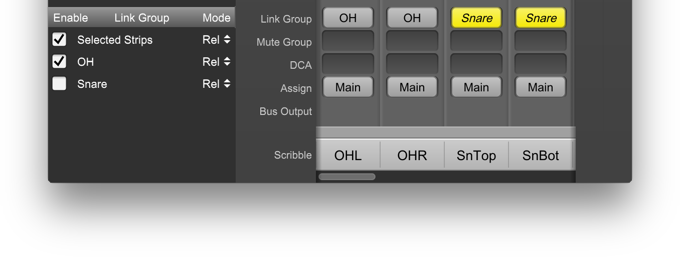
You can now <option>-click on the link-group assign of a strip to toggle the enable for the link groups that are assigned to that strip; this will be reflected in the Link Group pane as well.
If the link groups assigned to a given strip are all disabled, the link group assign for that strip will be drawn in a bypassed state.
You can now remove arbitrary Buses and DCAs by deleting the master strip associated with the bus or DCA. This allows you to use the same mechanism you use to remove input strips for Buses and DCAs. It also allows you to remove arbitrary buses and DCAs; before you could only remove buses and DCAs from the end of the list via the Configure Mixer dialog.
To Delete a bus or DCA, select the master fader strip for the bus or DCA, and the choose the Mixer > Delete Strips command.
The Monitor Controller now supports more ways of saving and recalling its state.
There are now two new commands in the Monitor menu:
You may use these commands to save and restore the configuration of the Monitor Controller for your domain to and from a file. Currently, there is no remapping available for these files, so they will only work properly with the domain that they were created with. When we have the remapping feature completed, it will extend to the monitor controller files as well.
We have also added support to allow you to optionally restore the monitor controller configuration from the state stored within the .cnsl3d file. Previous versions of MIOConsole3d did not save the monitor controller configuration in the .cnsl3d file, so this will only work with files saved with pb7 or newer.
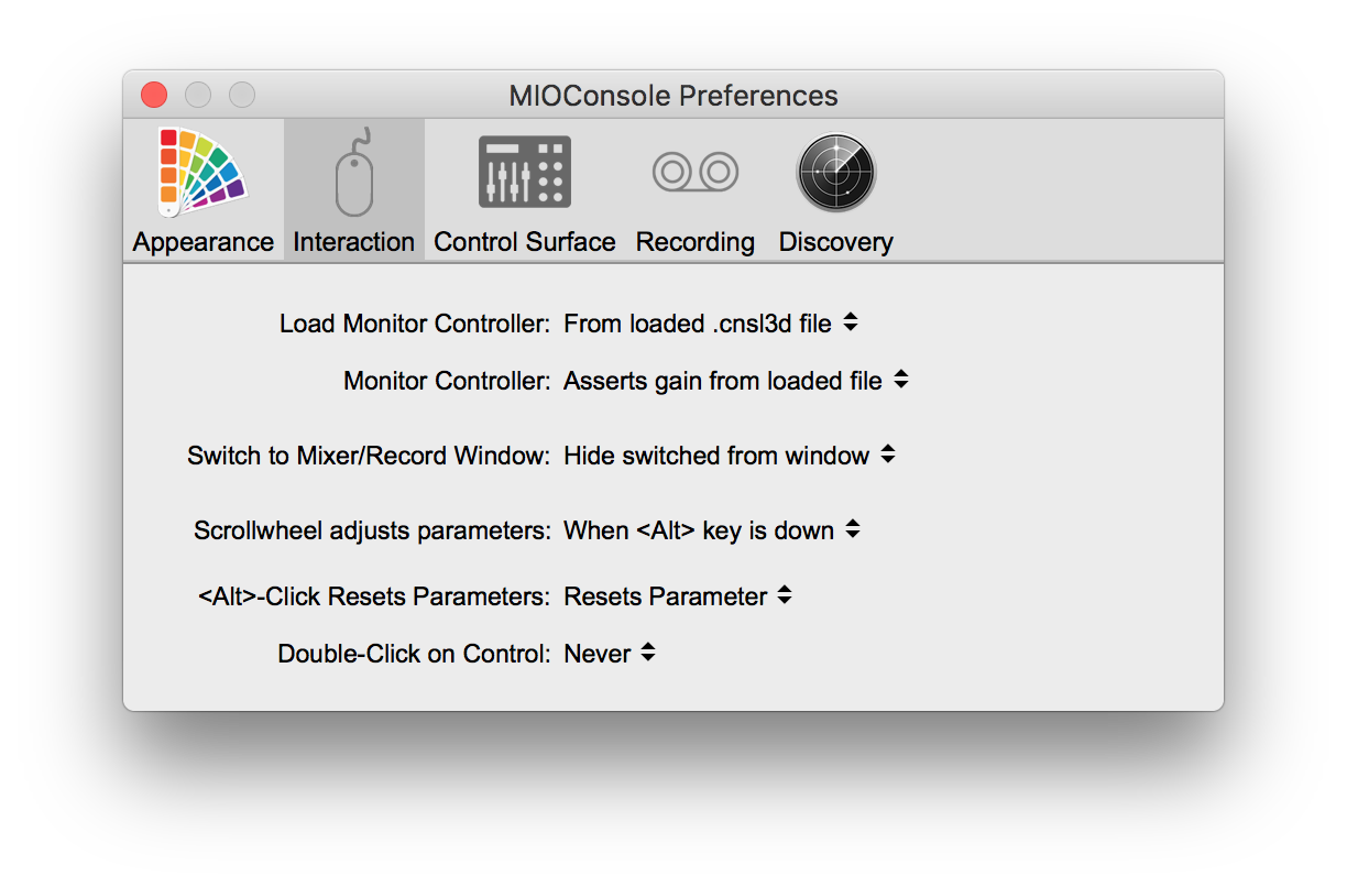
This is implemented as a preference: Interaction > Load Monitor Controller. You can choose to load from the .cnsl3d file (when you load a file), or from the global saved state (which is the old behavior). Loading from the global saved state will maintain your Monitor Configuration between files. Loading from the .cnsl3d file will allow you to have a tailored MC configuration per .cnsl3d file.
The Monitor Controller now validates Mix buses before attempting to access them; this fixes a crash that can occur when the saved MC state does not match the current mixer configuration. It now also properly manages the state of the Solo bus when the solo mode is set to Solo-in-place.
In certain situations the MC was affected by the Talkback Enable state; this should never happen and has been fixed.
The Enable Talkback and Enable Listenback commands are now available as menu commands in the Monitor Menu.
The Enable Talkback command is now only available if there is a Talkback source assigned. If the talkback source is unassigned, the Talkback will automatically be disabled.
The state of Enable Talkback and Enable Listenback are no longer restored from a saved .cnsl3d file, as this is not what you want and can lead to confusion.
We have made significant enhancements to the Record Panel engine and UI.
The Record Panel overview and streaming engine has received significant optimization and is capable of recording all 128 channels @ 192k, including to mirrors if the drives are fast enough, all at very low CPU load.
The Record Panel engine now utilizes the entire pre-roll buffer for buffering of audio when writes to the disk(s) take longer than expected. This allows for a substantial amount of buffering to occur while the system waits for the disk to catch up. The earlier version of the record panel could intermittently lose samples on some tracks when the disk was temporarily too slow to handle the write stream. This no longer happens.
Under certain circumstances the RP Engine could allocate memory in the audio callback which could cause intermittent CoreAudio overloads. This issue has been resolved.
The Rendering engine for the overviews in the Record Panel has also been heavily optimized and can now draw scrolling waveforms with low CPU overhead.
The Record Panel now has new Menu and Key commands to adjust the zoom factor of the overviews:
You can now choose to hide tracks that are routed to the computer, but not record enabled. To do this, check the Show only Record Enabled tracks in the Hamburger Menu in the Record Panel.
The trigger mode settings in the Hamburger menu and in the RP UI are now synchronized; before if you changed the setting with the menu, it was not propagated to the UI.
The Record Panel now has UI to show the Current Take number and the Next Take number. You can control the visibility of this UI element with the Show Take item in the Hamburger Menu in the Record Panel.
The Current Take is the take number for the take that is currently recording or has just ended. The Next Take is the take number that will be used when the next take starts. You can edit that take number by clicking on it; it will turn into an edit box and you can enter the new take number you would like to use.
Time Display section now has labels for all of the different time information that is displayed in the UI. The time displays now use cached glyphs for the digits in the display; this decreases the CPU load required to update the displays and also removes the annoying character width jitter that sometimes occurred as the displays were updated.
The Timecode section of the Time Display now shows the decoded timecode format as well as the actual timecode value. This will show the frame rate as well as the NDF/DF status.
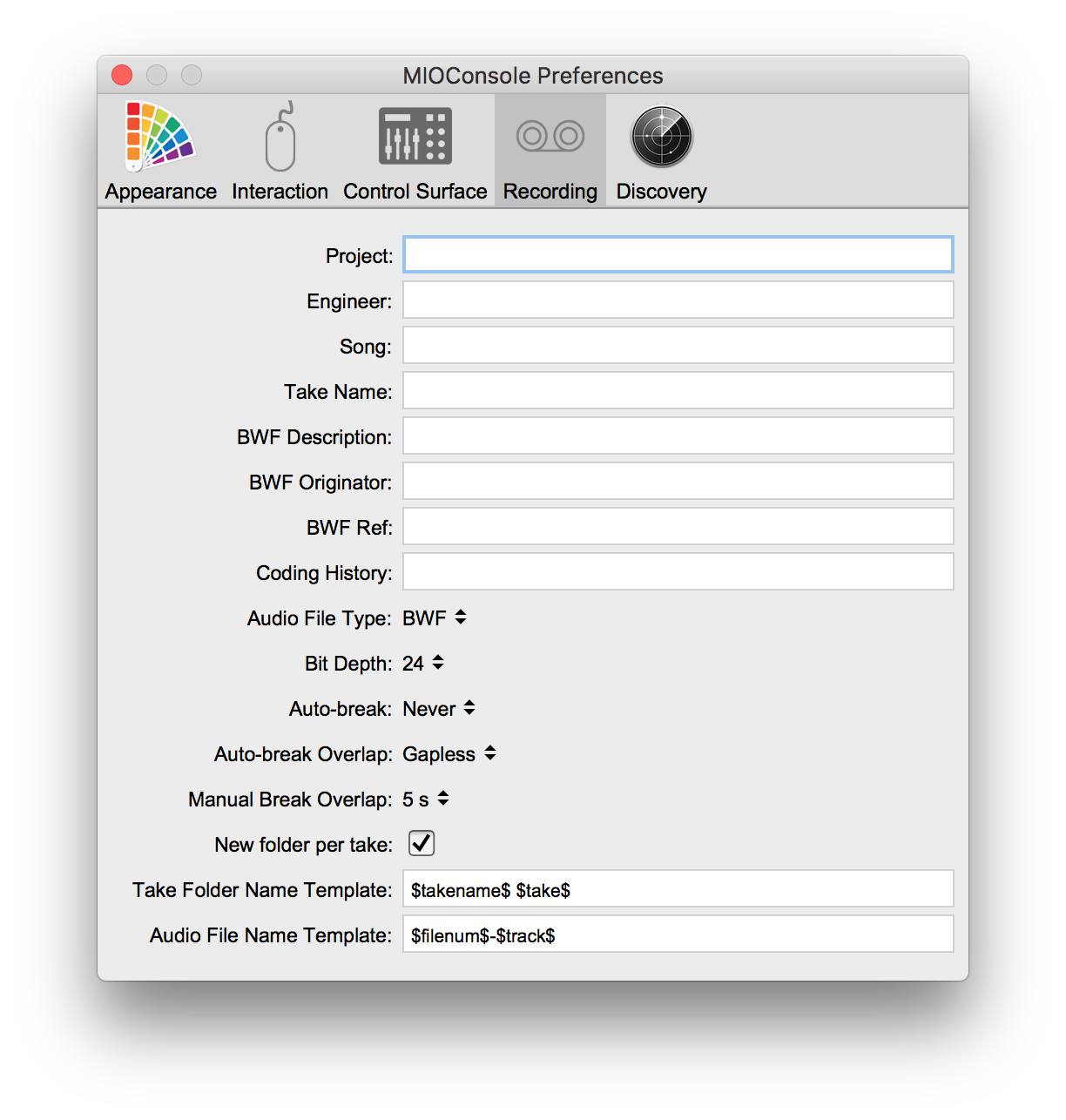
The Take field of the Recording preferences has been repurposed as the Take Name field. You can cause it to be inserted in the generated file or folder names by using the $takename$ token.
The various numeric tokens used for filename and folder name generation can now have an optional field width specified. The tokens that this applies to are:
For each of these tokens, you can add a .{number} after the token name, but before the closing $. So, for example you could use $take.4$ to indicate the take; that would cause the take number to always have 4 digits (e.g. 0001, 0002, ...). Without the optional field width the number will not have any leading zeros.
You can now specify an Auto-break file length. The options are: Never, 1GB, 2GB, 3GB and 4GB. While the files that the RP writes are not actually length limited, some older DAW and audio products do not properly support files that are > 2GB or > 4GB. So if you want the maximum compatibility or know that you will be targeting a DAW that doesn't support large files, you can set the autobreak to ensure that the files created by the Record Panel never exceed the specified length.
When the RP auto-breaks, it will trigger on the longest file in the take (e.g. stereo files grow faster than mono files), but it will break all the files in the take at the same instant.
You can control the overlap behavior of successive takes when an auto-break occurs with the Auto-break Overlap preference. This can be set to: Gapless or Pre-roll. When it is set to Gapless, the first sample of the new take will be the next sample that follows the last sample of the take that was broken. This allows you to butt the files up with no fades for continuous playback.
BWF files will be timestamped with either the selected LTC timecode or the TOD; the TC is guaranteed to be seamless across the breaks, so you can spot the files to their record times and there will be no gaps.
When Auto-break Overlap is set to Pre-roll, the RP will use your current Pre-roll time to overlap the new take with the take that was broken. The broken take ends at the point of the break, and the new take will start the specified pre-roll time before the break.
We have also added a new preference Manual Break Overlap that allows you to specify how much overlap there should be between a manually broken take (e.g. one where you hit the Record button while you are already in record) and the new take. As with the Auto-break Overlap, the broken take ends when you hit the Record button, and the new take starts the specified time before the previous take ends. If this is set to Gapless, then the break will be seamless.
MIOConsole3d now has the up-to-date versions of the 3d Firmware and the MHLinkDriver embedded within the application package. As a result, these are no longer included as separate files in the download.
With this change, MIOConsole3d knows the versions of the embedded components and can determine if they represent an update to the driver and/or firmware that is currently installed on your system.
For the Firmware, the version is checked per unit, and when MIOConsole3d determines that the firmware on a given unit should be updated, it will draw the firmware version for that unit in the MHLink Domain panel in an amber/orange color. This allows you to tell, at a glance if there are updates available for your boxes.
If the firmware version number indicates that an update is available, you can click on it, and that will initiate the firmware update process (after displaying a confirmation dialog that tells you which version the firmware will be updated to). Remember, you must power cycle or reboot your boxes for the newly installed firmware to be used.
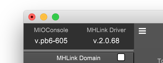
For the MHLink Driver, MIOConsole3d will check the version against the version of the driver that is currently running on your system. If there is no driver installed, or if it is older than the one included with MIOConsole3d, the Driver version number in the version header displayed in the top-left corner of the Mixer window will be drawn in amber/orange.
As with the firmware, clicking on the Driver version number will initiate the installation process for the new driver (after displaying a confirmation dialog).
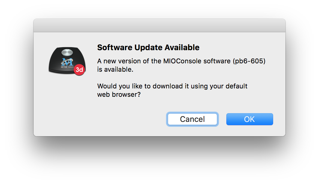
MIOConsoled3d can now check to see if a new version is available for download. If a newer version of the software is available, the MIOConsole version number displayed in the upper left hand corner of the Mixer window will be drawn in an amber/orange color. This allows you to tell, at a glance if there is a software update available.
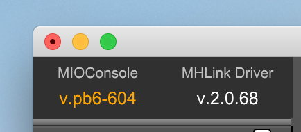
If the MIOConsole version number indicates that an update is available, you can click on it, and that will initiate a download of the software update using your default web browser (after displaying a confirmation dialog that tells you which version will be downloaded). After the download is complete, you can replace the old version of the software with the newly downloaded version at your convenience.
MIOConsole3d now checks to see if your connected boxes are registered with Metric Halo, and lets you know if there are an un-registered boxes. Even if you registered your boxes before upgrading them to 3d, the Console will indicate that they should be registered again, as the serial number for your unit(s) changed.
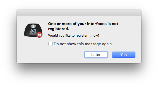
You can register your hardware directly from MIOConsole3d, either by clicking on the "Yes" button in the notification alert or by selecting the MIOConsoled3d > Register Attached Units… menu command.
While you can defer registration and even disable notification, we strongly recommend that you register your hardware with us as it greatly helps in the support and development process and allows us to serve you better in the future.
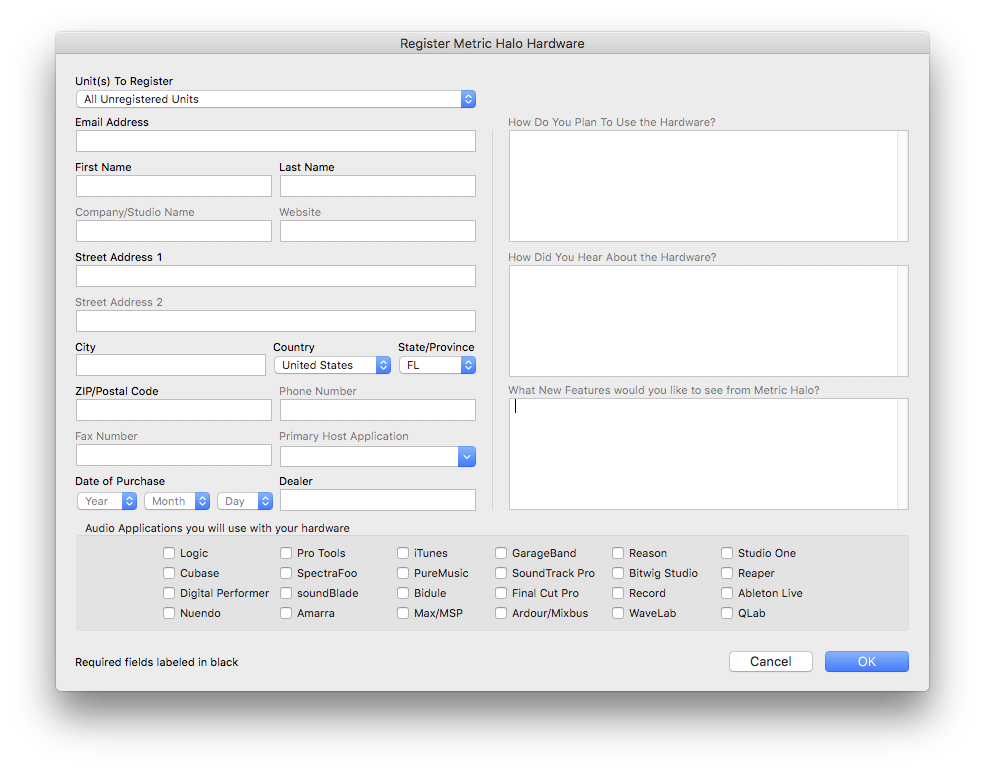
All the information you provide as part of your registration is kept private by Metric Halo and is not shared with or sold to third-parties.
We have reworked important elements of the USB implementation in the firmware in order to provide more stability and more functionality.
The UAC device now can reliably transport audio and MIOConsole meter and control data at sample rates higher than 48k. With the previous version, running MIOConsole3d at the same time as running audio transport at sample rates > 48k would lead to clicks, dropouts and grunge. This no longer happens.
If the USB audio device was streaming and the sample rate was changed via a method other than through the CoreAudio device, that could cause the USB device to stop communicating and would require a reboot. This has been fixed.
Due to a configuration issue, if the 3d device changed sample rate that change was not reported to the USB host and as a result audio would play off-rate or would be distorted. This has been fixed.
We have added the ability to configure (persistently) the number of input and output channels that are reported to the USB host. This allows you to trade off USB channel count for sample rate capabilities. You can set the channel count up to 48 channels, in steps of 4 channels. The S/R break points are as follows:
To change the available channel count over USB, <right>- or <control> click on the unit's pane in the MHLink Domain panel to popup the unit menu:
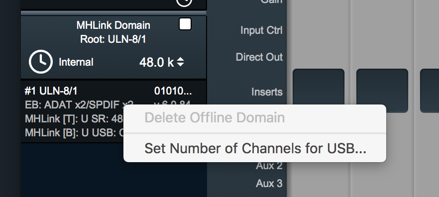
Selecting Set Number of Channels for USB… will show the USB Channel Configuration box:
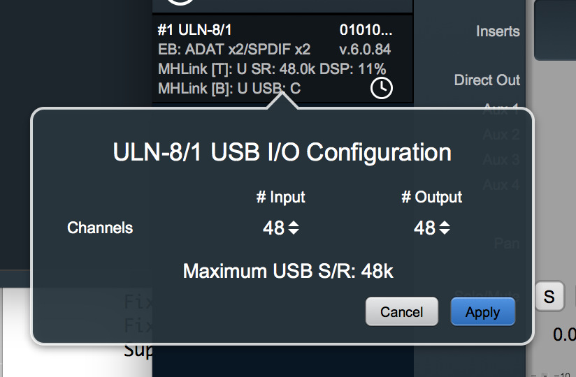
You can choose the I/O config for the input and output independently. The side with the highest channel count will determine the S/R limit. When you set this configuration, the setting is stored in the box persistently, and will be recalled the way you have it set on each boot, without having to re-set it from MIOConsole3d.
If you do not need to use higher sample rates, this is will give you the capability to stream more channels to and from the box over USB.
Earlier versions of MIOConsole3d would get confused if you connected both MHLink and USB to the same computer. This version handles this configuration much better out of the box, but certain actions on your part will still cause the console to become confused (specifically, rebooting a unit that is connected both ways when MIOConsole3d is running; this occurs because the USB connection comes up before the MHLink connection, but the MHLink connection is preferred).
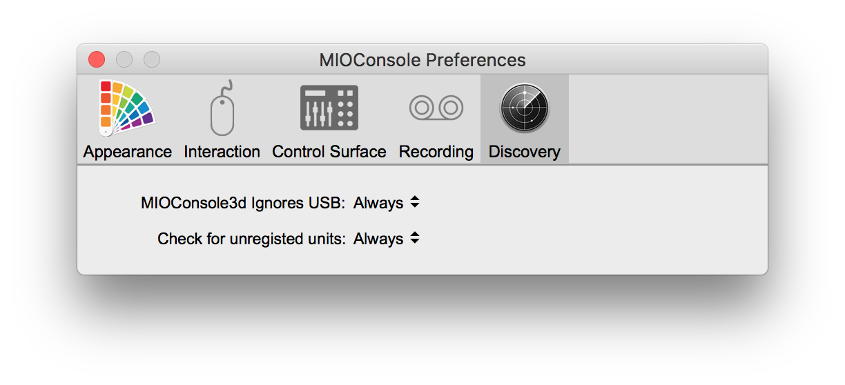
If you intend to regularly use your box with both connections in place, you can tell MIOConsole3d to ignore the USB connection. That will allow you to control a multi- (or single) box MHLink domain, even though the USB connection is present. Combined with SCP, you are still able to fully route the USB connection via MIOConsole3d, and combined with the USB Channel count configuration, you can route substantially higher channel counts over USB if you are running at lower sample rates.
In order to have MIOConsole3d to ignore the USB connection you can set the
preference to Always. If you do choose this setting, MIOConsole will only see 3d units over MHLink; it will not connect if only the USB connection is in place.
Configuring MIO Console in this way allows you to have a multi-box domain connected (potentially with other computers connected to the downstream unit SCP/USB ports) and still use USB for audio transport on your more latency sensitive I/O. It also enables the use of the MIDI port(s) on the directly attached unit as these are exposed over USB (but not yet exposed over MHLink).
We were able to substantially optimize the MHLinkDriver which decreases the CPU required by both the driver and the coreaudiod, especially at large channel counts and high sample rates.
We also tuned the CoreAudio watchdog process to give hosts more time to get samples to the driver; this solves a set of drop out issues that could occur when a host was late in providing samples in the buffer period.
We have also identified and eliminated an issue that could, intermittently, lead to kernel panics, especially when connecting or disconnecting a box.
We have also identified and eliminated an issue that, especially when Apple's Power Nap was active (which appears to be the case even when it is disabled), could lead to a box partially mounting over Ethernet and the associated interaction causing the box to crash, necessitating a reboot of the box. This same issue could intermittently cause boxes to not mount in MIOConsole on first attach/power up.
We have also added support for Jumbo Ethernet packet support to the MHLinkDriver.
The standard maximum packet size on Ethernet is 1500 bytes. This limits the number of sample frames we can place in a given MHLink packet and causes the packet rate between the computer and the box to be quite high.
While the MHLink hardware is not affected by the packet rate (as all the packet processing is done in dedicated hardware), the high packet rate does cause the low level Ethernet NIC driver in the computer to do a lot of work, and it uses a lot of CPU as a result.
By utilizing Jumbo packets (e.g. packets larger than 1500 bytes), we can decrease the rate that packets are sent to and from the computer and substantially reduce the overhead that is generated by the low-level Ethernet driver.
This version of the MHLinkDriver will automatically utilize packets up to the maximum specified (the Maximum Transfer Unit or MTU) for the underlying NIC driver. Since every device on an Ethernet network needs to agree on the MTU, this is only useful if you will dedicate an Ethernet port to MHLink, or if you are already running a network with a larger than normal MTU.
In order to use this feature, you need to manually configure the MTU for the Ethernet interface that you use for MHLink:
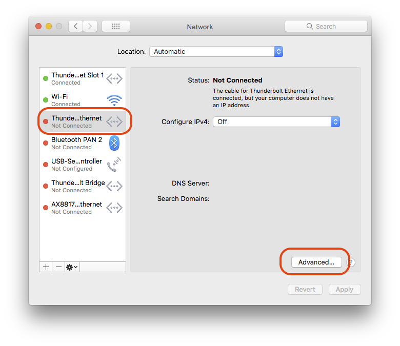
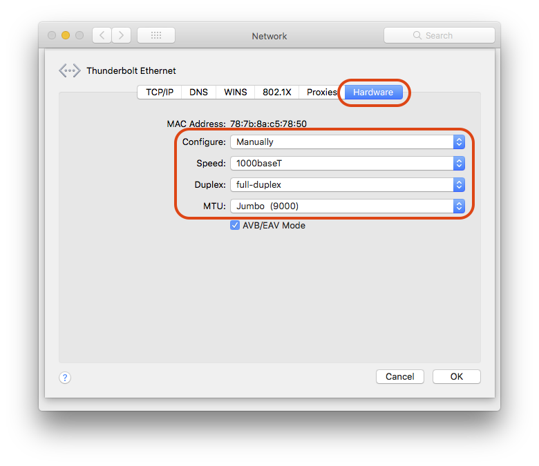
This is an optional optimization you can choose to do with a dedicated Ethernet connection for MHLink. It is not required.
This guide covers the basics. Many of the items not explicitly covered are very similar to 2d or are relatively self evident. We'll be updating the documentation over the coming weeks to include more items and to address things in more depth.